Aeropendulum — Inverted Pendulum Control
Implementation of a PID controller with lead compensator to stabilize an aeropendulum at 180°, combining Root Locus and frequency domain design methods.
Aeropendulum — Inverted Pendulum Control
Overview
Implementation of a PID controller with lead compensator to stabilize an aeropendulum at 180°, combining Root Locus and frequency domain design methods.
Overview
The aeropendulum is an inverted pendulum system where a motor-driven propeller mounted at the end of a rigid arm provides the actuation force. Unlike a classic pendulum at rest (0°), the control objective was to drive and stabilize the system as close to 180° as possible — the upright unstable equilibrium point.
This project covered the full control engineering cycle: mathematical modeling, controller design, simulation in Simulink, and physical implementation on an Arduino Uno.
Plant Description
The system consists of a rigid arm free to rotate, with a brushed DC motor and propeller at one end providing aerodynamic thrust. The arm angle is measured by an AS5600 magnetic encoder, which provides smooth and precise angular feedback. A MX1919 H-bridge drives the motor bidirectionally, allowing thrust control in both directions.
| Component | Details |
|---|---|
| Actuator | DC motor + propeller |
| Driver | MX1919 H-bridge |
| Sensor | AS5600 magnetic encoder |
| Controller | Arduino Uno |
| Control objective | Stabilize at 180° (upright position) |
Controller Design
A PID controller with lead compensator was implemented. The proportional and integral gains were designed using Root Locus and frequency domain techniques, ensuring adequate phase margin and steady-state performance. The derivative gain was tuned empirically to reduce overshoot without amplifying noise.
| Parameter | Value | Design Method |
|---|---|---|
| Kp | 0.8 | Root Locus |
| Ki | 0.5 | Frequency Domain |
| Kd | 0.04 | Empirical tuning |
| Lead Compensator | Yes | Phase margin improvement |
Simulation
Prior to physical implementation, the closed-loop system was simulated in MATLAB/Simulink to validate the controller design, tune parameters, and analyze step response characteristics including rise time, overshoot, and settling time.
Results
The implemented controller successfully stabilized the aeropendulum near the 180° upright position. The AS5600 encoder provided reliable angle feedback, and the lead compensator improved the transient response compared to a pure PID design.
Code Files
Aeropendulum PID Controller
System response — stabilization at 165°
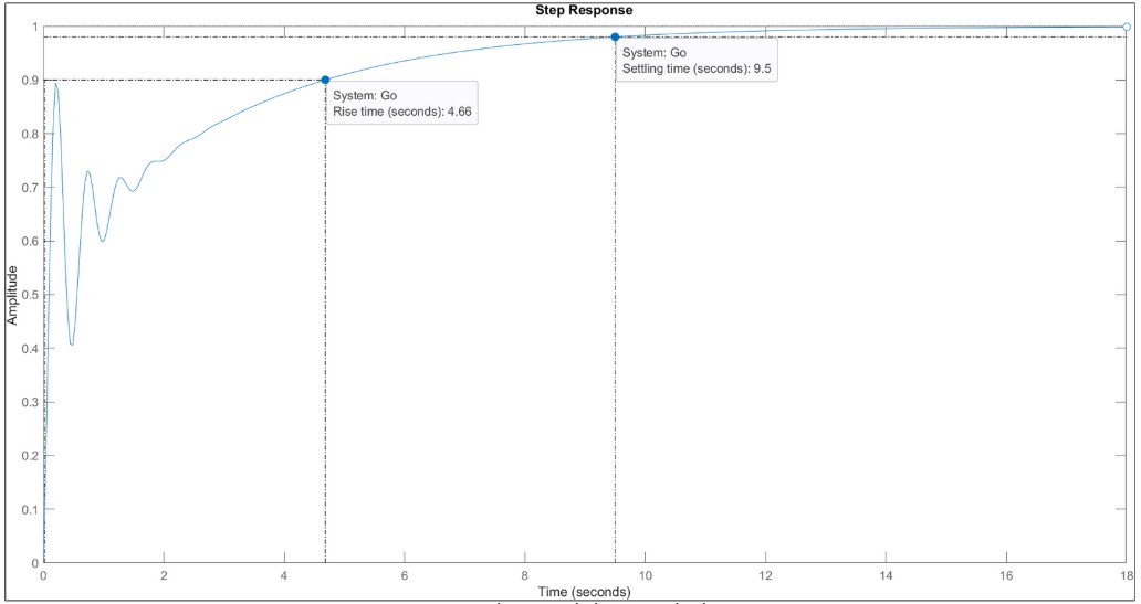
PID step response
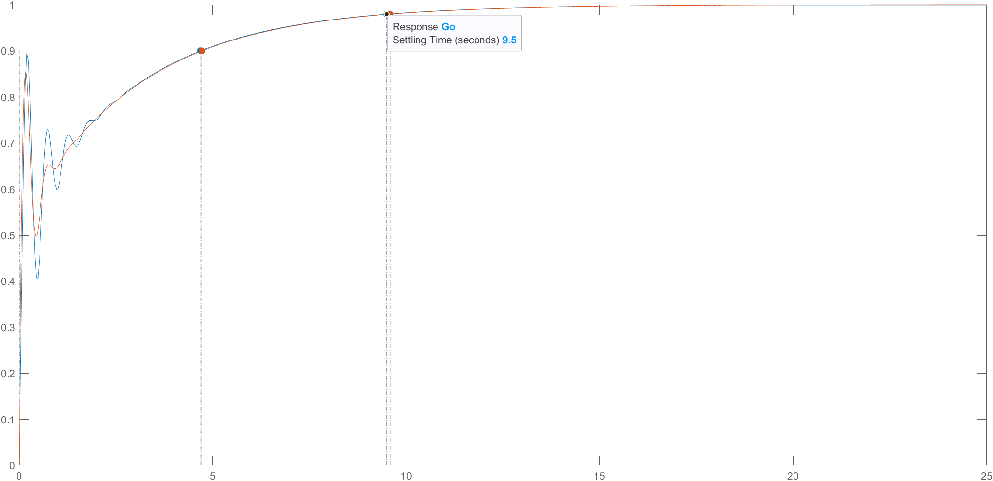
PID + lead compensator response